Back in November of 2024, my father (who is now 86) moved in with us. We are lucky enough to have a house with a basement apartment, and after my mother died we were able to take him in.
As an older person he has certain needs, so I’ve been looking for technology that could help out with taking care of him. At first I just wanted to get a couple of low cost buttons that he could press to send me a notification. I could put one next to his bed, next to his chair, next to his desk and in the bathroom, etc., and if he needed me he could just hit the button and I would get a notice.
This search led me to Sonoff and their Zigbee-enabled devices. These are low cost, low power devices that can do a number of simple tasks (such as implement a button). They integrate with Home Assistant (HA), which is a platform I am starting to explore as an alternative to Apple’s HomeKit ecosystem.
TL;DR; If you are willing to open up the Sonoff Zigbee Bridge Pro and flash custom firmware, it is pretty easy to integrate Zigbee devices with Home Assistant. Just use the Zigbee Home Automation integration and avoid MQTT.
They had the buttons I needed, and while I was window shopping I picked up a temperature/humidity sensor and a couple of human presence sensors. The temperature sensor was just for fun, but the human presence sensors would let me know where he was in the apartment without the intrusiveness of cameras.
To make this all work I needed a bridge device, so I bought the Zigbee Bridge Pro.
Now Sonoff has its own cloud-based device management system based around an app called eWeLink. I installed it and confirmed that the buttons would do exactly what I wanted: in case of a button press, I could get an alert.
But being an open source nerd I didn’t want to rely on a third party server, so I went exploring to find out what it would take to integrate this new hardware with Home Assistant. The articles I read all started off with flashing a new, open source firmware, called Tasmota, on the Zigbee Bridge.
Note: since I spent several days on this process I did come across a Home Assistant Add-on that will integrate HA directly with eWeLink. So if you are cool with using a remote server that could be an easier way of integrating Sonoff devices with HA.
In order to flash new firmware, you will need to open up the box and connect a TTL adapter directly to the motherboard. You will not need to solder anything and you only have to do this once, but it is a little more involved than just connecting the device to a computer.
While I had all of the needed hardware on-hand, I didn’t really have time to work on this, but since my work situation has changed lately, I was able to devote a couple of days to it. I spent most of that time down a rabbit hole that I could have avoided entirely (sigh).
Flashing Tasmota to the Bridge
In order to flash the firmware, you will need the following hardware:
- Sonoff Zigbee Pro Bridge (’natch)
- USB to TTL Serial Adapter
- Jumper Wires
- Small prying tool (a small screwdriver will work)
- Phillips head screwdriver
As for software, you’ll need the latest tasmota32-zbbrdgpro.factory.bin image from GitHub. You will also need the ESP_Flasher tool. You can use the esptool package under Linux as well, and I can highly recommend this post by Stephen Grier which I referred to a lot during this process if you want to go that route.
With that in hand, let’s get going.
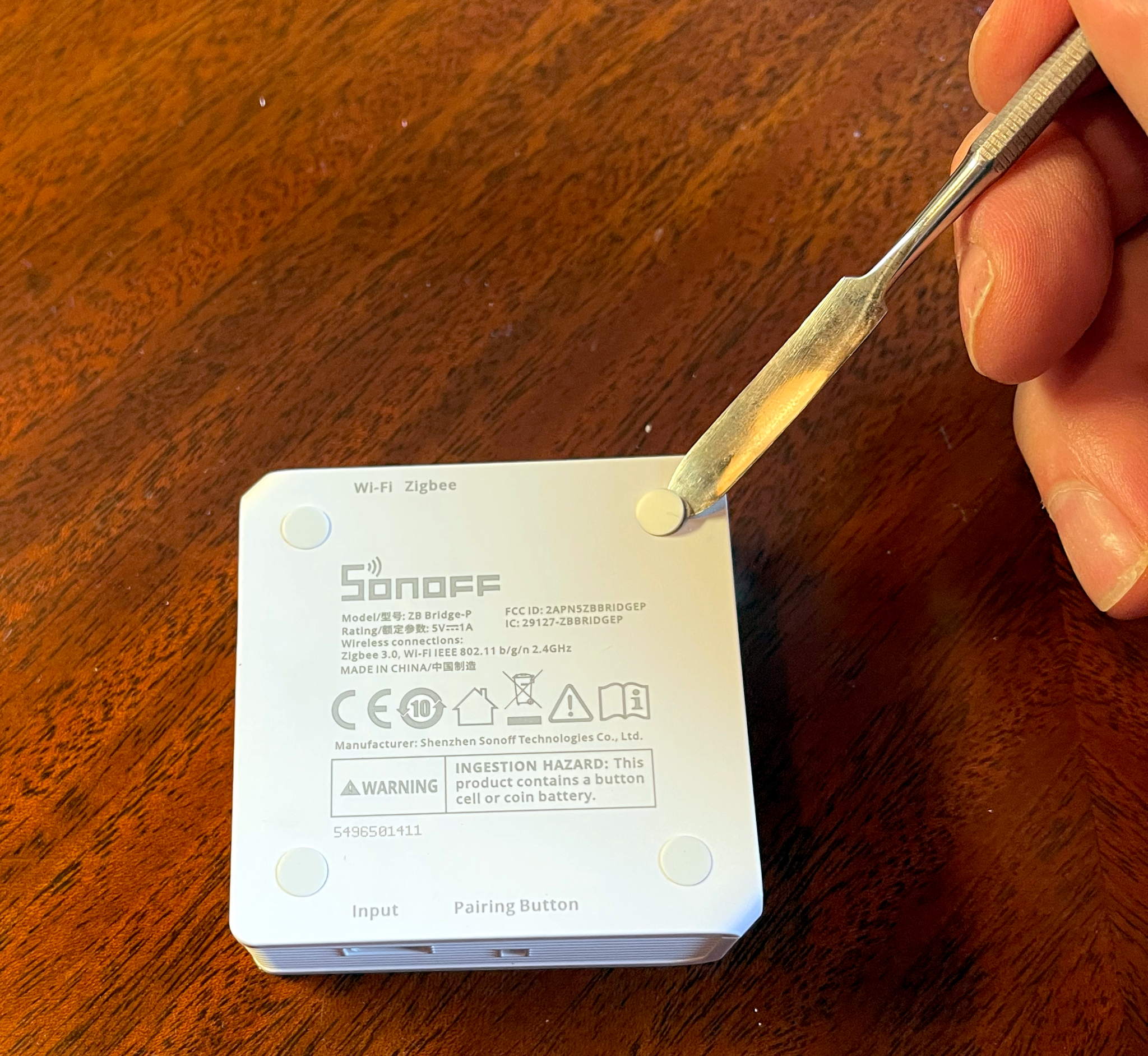
Start by prying off the little white rubber pads on the bottom of the Bridge.
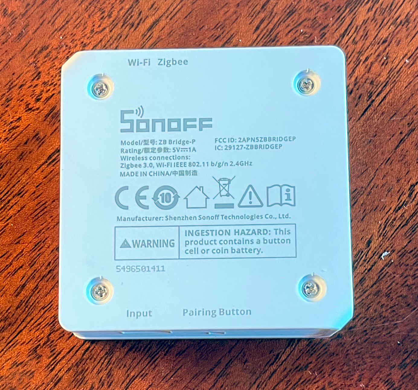
This will expose four Phillips head screws. They are “captive” in that they won’t come out of the plastic back plate, so just loosen them until the plate separates from the rest of the case.
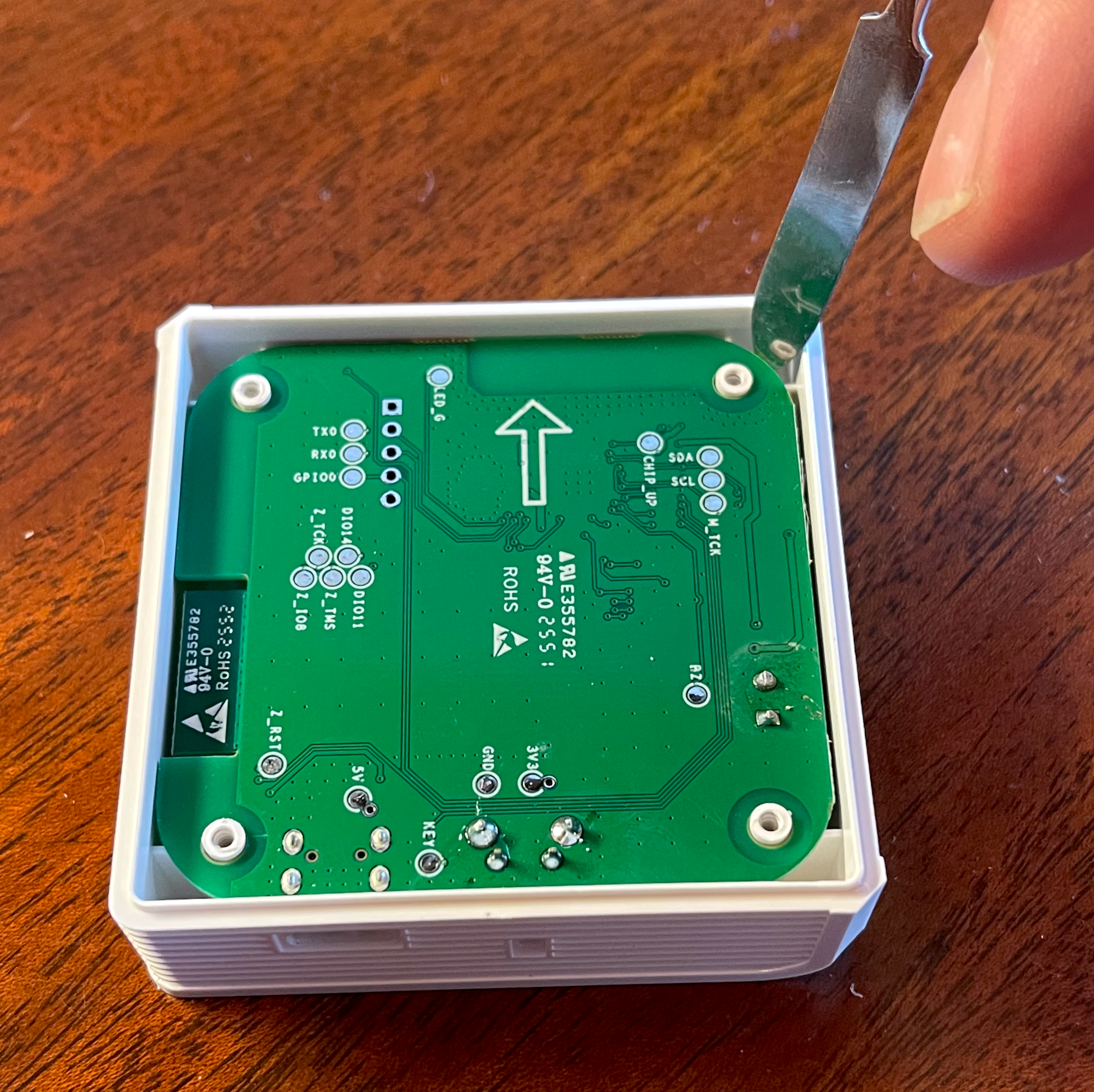
You can then remove the green circuitboard. Gently pry up on the side away from the USB port and it should come right out.
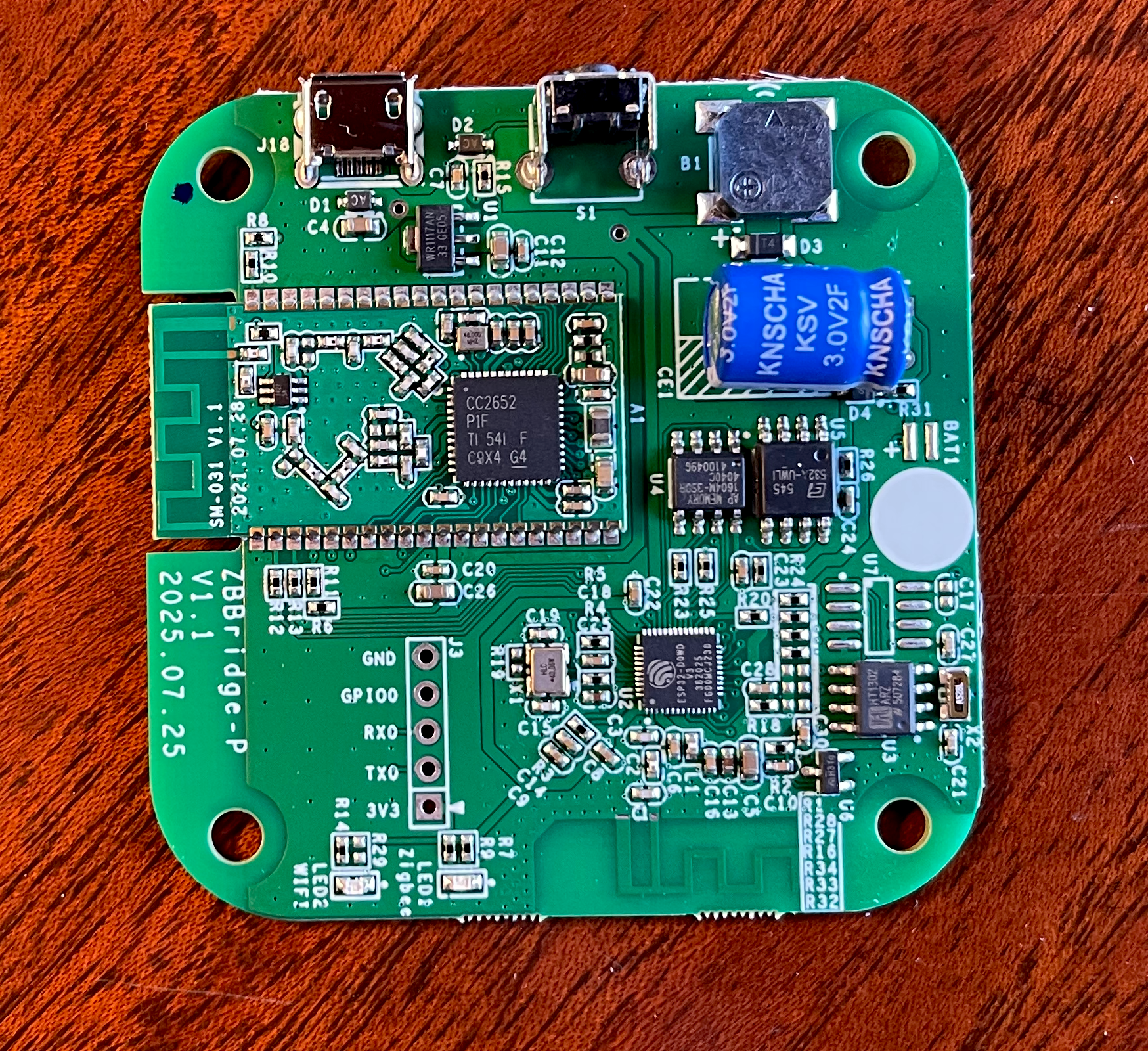
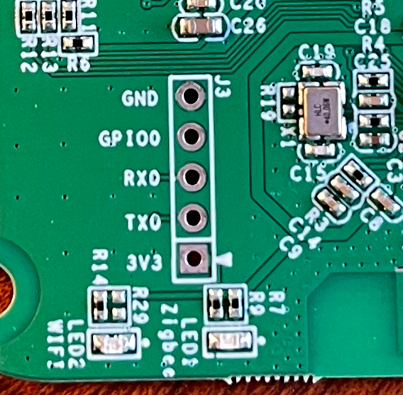
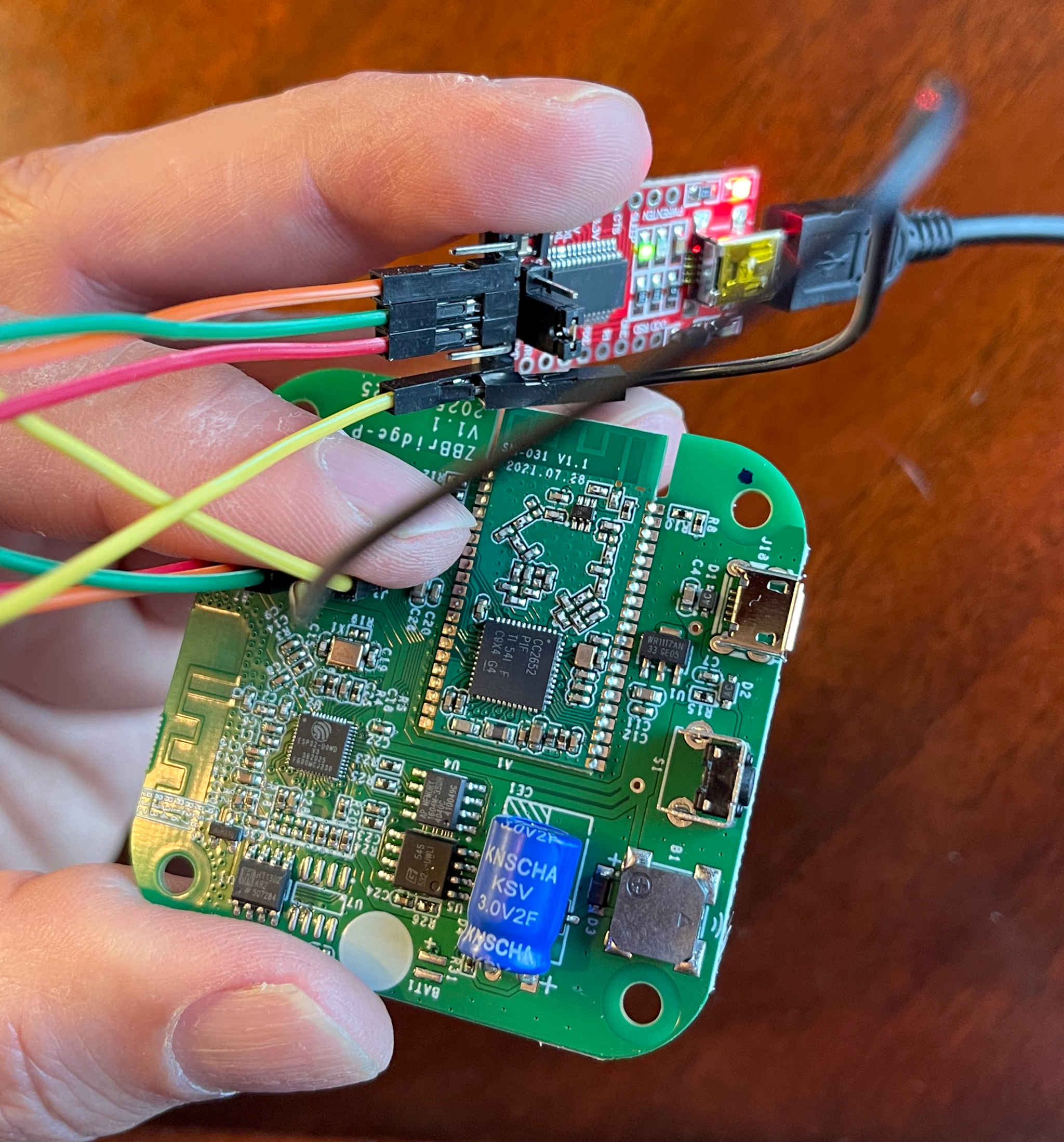
If you look on the component side, on the part of the board opposite the USB power connector you’ll see five little holes. You are going to be connecting jumper wires from the TTL adapter into those five holes.
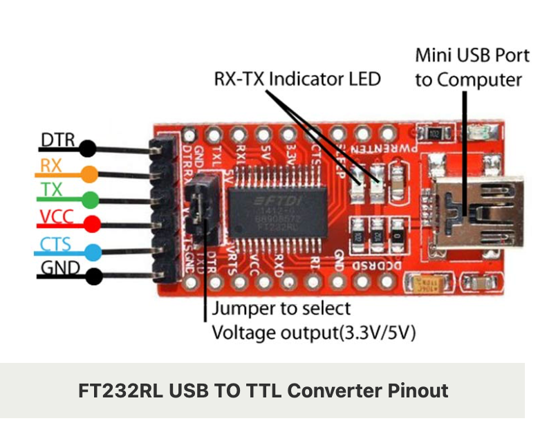
Before doing anything, look at your TTL adapter and see if there is a jumper that selects between 5V and 3.3V. You want to set it to 3.3V. This adapter will be powering the Bridge while you are flashing the hardware.
My TTL adapter came with six pins. It was a little hard to see the labels, but I needed four of them: TX, RX, VCC and GND.
With the voltage on the adapter set to 3.3V, connect the VCC pin to 3V3, the TX pin to RX, the RX pin to TX, and the GND to GND. In order to flash the firmware, the GPI00 has to be tied to GND when you apply power, so I just wedged in another wire to my GND connector on the adapter and plugged it in to the GPI00 hole (I started with this older YouTube video that shows you how to do it).
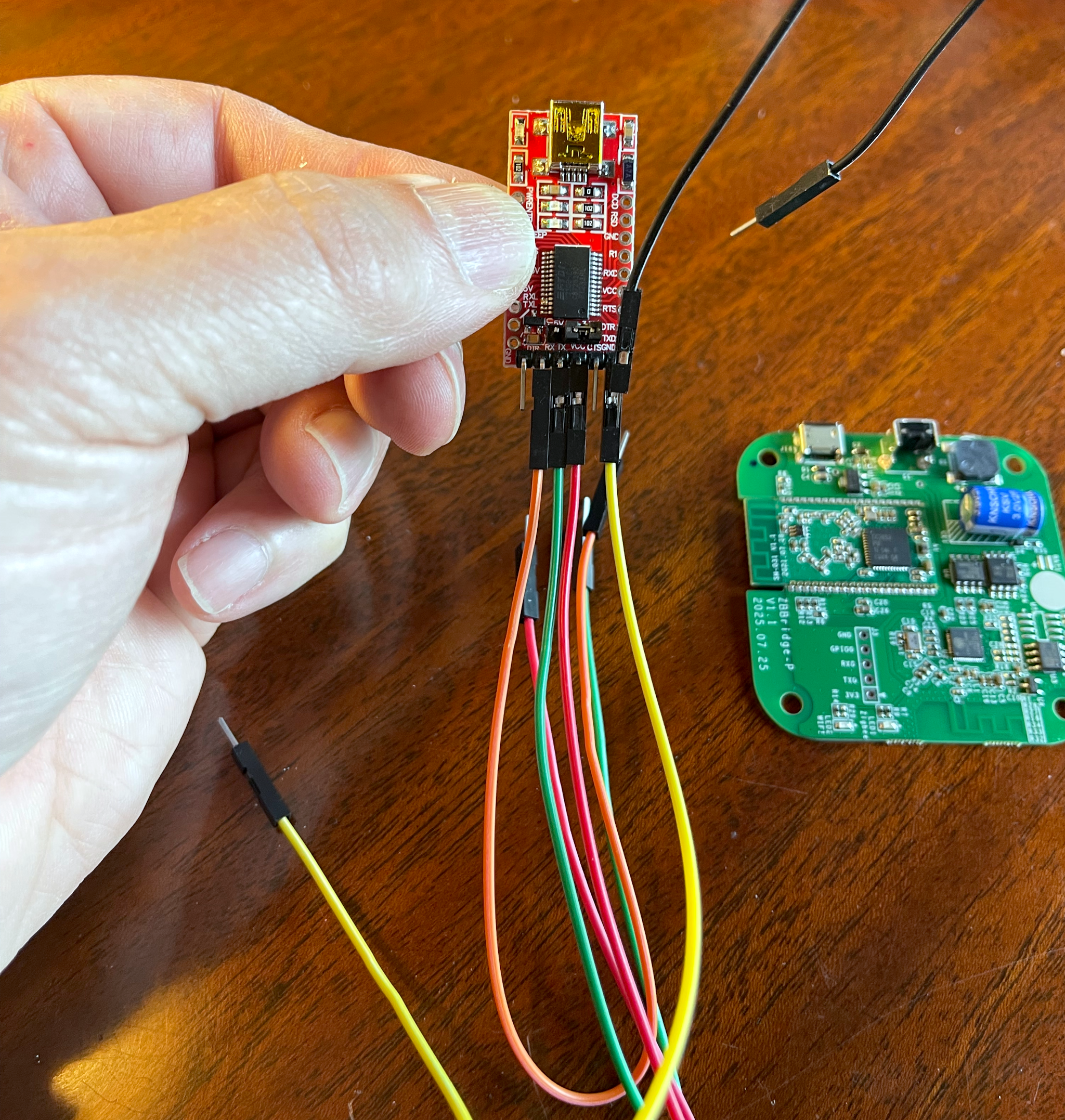
This is the tricky part, because the pins will want to come out. I just used my finger to hold them in place.
When you think you have everything ready, but before you connect the TTL adapter to your computer, launch the ESP_Flasher application. There will be a “Select Port” dropdown. Click on it and note the available ports. When you connect the adapter you’ll get a new port and that is the one you want to use. Quit out of the application for now.
Connect the adapter to power, and you should see a red light on it as well as a blue light on the Bridge. Launch the ESP_Flasher tool, choose the new port and click on “Connect”.
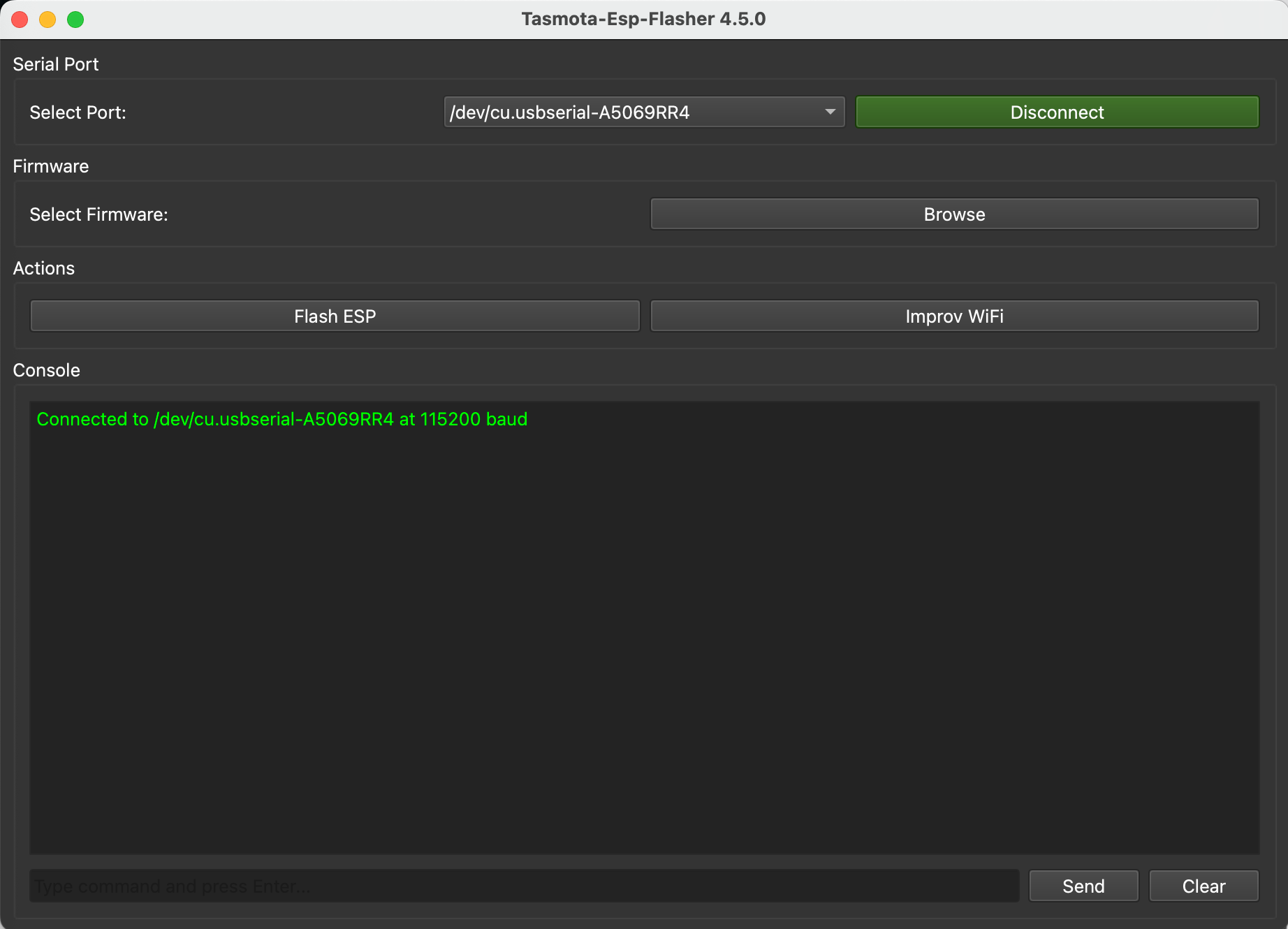
If the connection goes through, you are ready to flash. Browse until you find your downloaded tasmota32-zbbrdgpro.factory.bin image, select it, and click on “Flash ESP”.
If everything goes well you should see messages as the flashing proceeds. It should take a minute or two, and the times I did it, it would hang on 90% for a few seconds (I got worried because the progress indicator moved pretty quickly up until then).
When it is complete, disconnect the power to the adapter and remove the wires.
If it fails and complains about a communication issue, swap the wires for RX and TX. Remember that the “receive” port on one device needs to connect to the “transmit” port on the other, and vice versa.
At this point in time you can reassemble the Bridge. Gently place the board back in the enclosure (making sure the USB port fits into the hole) and screw on the back plate. I would not replace the little rubber feet (they are sticky on one side) until you make sure everything is working just in case you have to try again.
Booting into Tasmota
If everything has gone smoothly up until this point, the rest is easy. Connect the Bridge to power (you should see a blue light come on briefly), wait a minute or so, and you should see a new wireless SSID that starts with “Tasmota”.
Select that network, and on my iMac it brought up one of those authentication screens that you get when, say, connecting to hotel WiFi. If not, the IP address should be 192.168.4.1.
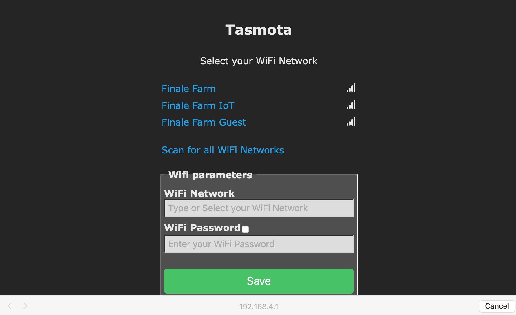
This screen will let you connect the Bridge to your local WiFi network. Once there, choose the network and enter in the password. It should then show you the new IP address for the Bridge. Switch back to your main network.
Note that one of the first things I do with any device I add permanently to my network is I assign a static IP address to it. The process differs depending on what router/DCHP server you use, so if you know what I’m talking about you should do it, too.
Navigate to the new IP address and you should see a screen like this:
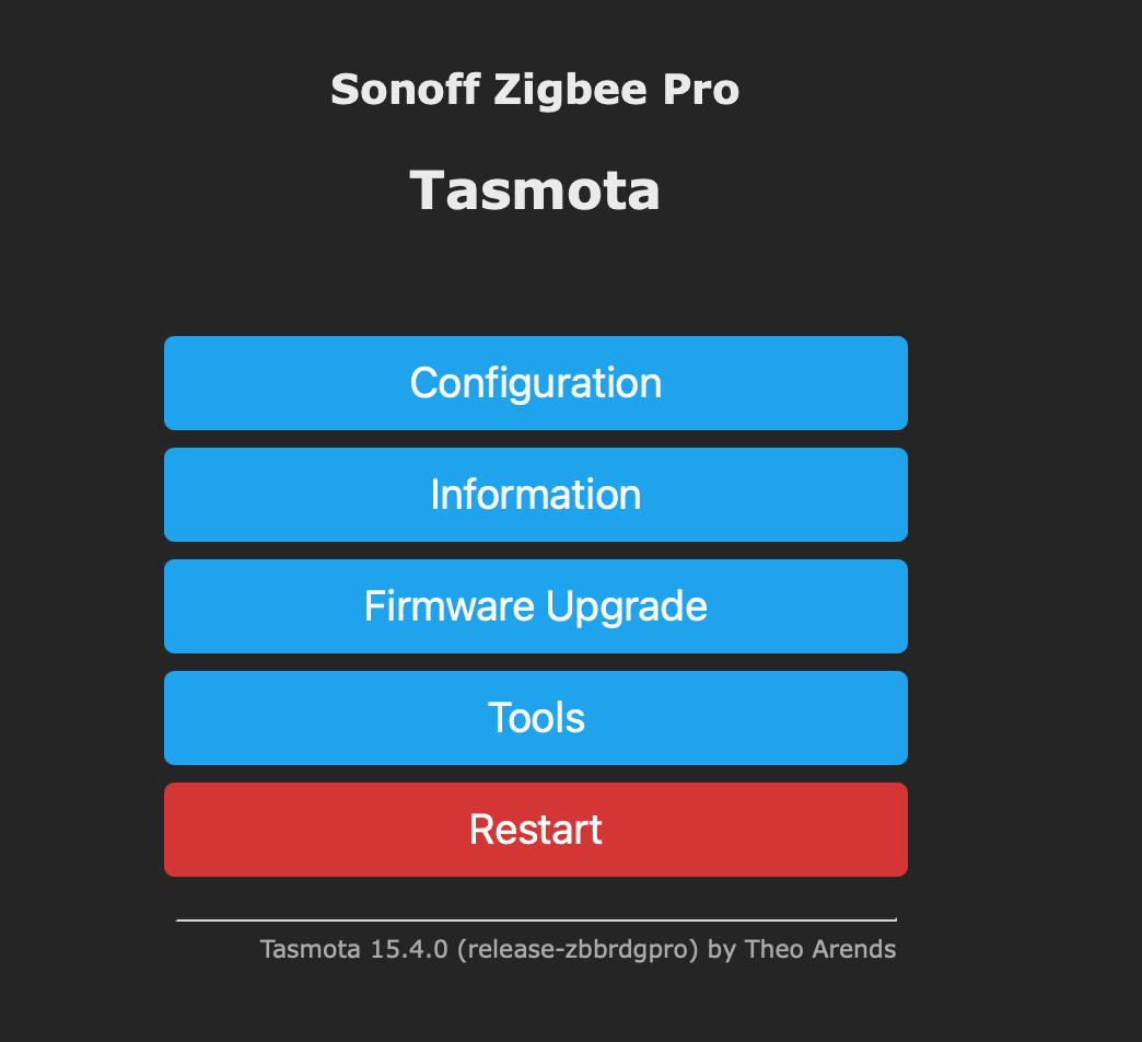
If you made it to this point you can probably put the little rubber feet back on.
What Not to Do
At the point in time I embarked on two days of messing around trying to get this stupid thing to integrate easily with HA. I sometime joke when it comes to tech that I “don’t know how the muggles do it” as I consider myself somewhat savvy, and I totally messed this up.
Everything I read talked about connecting Tasmota to HA via MQTT. You install an MQTT server on HA, create a user, and point the Tasmota to the server using that username and password.
You then have to install a configuration file which will then allow the Tasmota device to discover (pair) with Zigbee devices, and then events from those devices will show up via MQTT.
Oh, and you’ll see a lot of references on the web to going into the console and running “SetOption19 0” to make discovery work.
The problem: discovery doesn’t work.
You can look at the MQTT queue and you will see a “tele/discovery” message for the Sonoff Bridge itself, but never for any of the devices connected to it.
Instead, you have to edit the configuration.yaml file in HA and manually add the devices. It’s a pain. Here is an example for the temperature/humidity sensor:
mqtt:
  sensor:
    - name: "Basement Temperature"
      unique_id: "Basement_Temp"
      state_topic: "tele/tasmota_01/Basement_Temp/SENSOR"
      value_template: >
        {% if value_json['ZbReceived']['0x1B5C']['Temperature'] > 0 %}
          {{ (value_json['ZbReceived']['0x1B5C']['Temperature']|float * 1.8) + 32 }}
        {% else %}
          {{ states(entity_id) }}
        {% endif %}
      unit_of_measurement: "°F"
      availability_topic: "tele/tasmota_01/LWT"
      payload_available: "Online"
      payload_not_available: "Offline"
      device_class: "temperature"
    - name: "Basement Humidity"
      unique_id: "Basement_Humidity"
      state_topic: "tele/tasmota_01/Basement_Temp/SENSOR"
      value_template: >
        {% if value_json['ZbReceived']['0x1B5C']['Humidity'] > 0 %}
          {{ value_json['ZbReceived']['0x1B5C']['Humidity'] }}
        {% else %}
          {{ states(entity_id) }}
        {% endif %}
      availability_topic: "tele/tasmota_01/LWT"
      payload_available: "Online"
      payload_not_available: "Offline"
      qos: 0
      device_class: "humidity"
      expire_after: 86400
      unit_of_measurement: '%'
I got stuck working on the buttons and the human presence sensor, and in researching it I kept finding all of these articles about it “just working”.
I finally posted a message to the Tasmota discussion forum on GitHub and a person named sfromis pointed me in the right direction.
This doesn’t mean that doing all of this extra effort wouldn’t work, but there was a much easier solution.
Using ZigBee Home Automation
The trick is to use the ZigBee Home Automation (ZHA) integration in HA.
Go back to the Tasmota interface and click on “Configuration” and then “Auto-Conf”. My guess is that you will be running the “Sonoff ZBPro” configuration. Select a new auto-configuration from the drop down labeled “Sonoff ZBPro TCP”. Apply it and the device should restart.
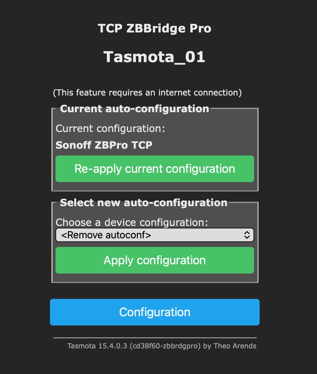
This will put the Sonoff Bridge into a mode where it can be controlled over the network directly from ZHA. And that’s it - you’re done messing with Tasmota.
In the HA user interface, go to Settings and then Integrations. Search for and add “Zigbee Home Automation”. When it is installed, configure it and choose to manually add the serial port. Enter in socket://[Tasmota IP Address]:8888 and the it should connect and complete the setup. Here is an older post with more information.
You can then navigate to “Settings” then “Zigbee” and choose “Add Device”. This will bring up pairing mode so you can press the pairing button on your Zigbee device and, bam, it will be added.
Easy peasy.
Final Reflections
After spending several days on this, I still haven’t configured the buttons that started me on this journey. I verified that they worked but I want to progress more in my journey from HomeKit to Home Assistant before putting them in front of my Dad (for now, he carries a whistle).
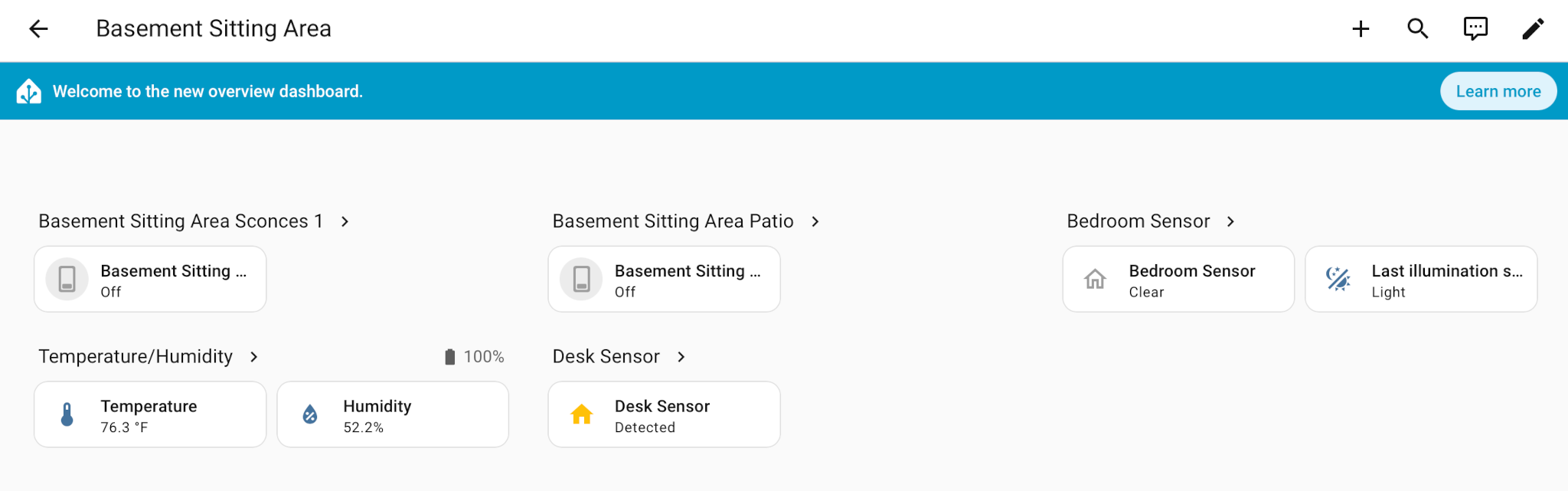
But the devices I do have configured work fine. I can read the temperature and humidity in his apartment (he likes it warm), and I can tell if he is at his desk or in bed, without using cameras.
It might have been easier to have simply bought a Zigbee USB dongle and plugged it right in to the Raspberry Pi running HA, but those have limited range. Now that I understand how it all works, I’ll probably buy some more Zigbee bridges and devices and put them around the farm (say, in the barn). Being able to use the Bridge over WiFi will make that possible.
Many thanks to the folks who went before me, and I hope that others find this useful in their own Zigbee journey.